Jumat, 08 Mei 2015

voltage source resonant

Rangkaian Voltage Source Resonant


Rangkaian ini paling banyak dipakai oleh berbagai industri ballast elektronik saat ini. Tegangan AC sebagai tegangan suplai disearahkan dengan mengggunakan bridge DR dan akan mengisi kapasistor bank C1.  C1 akan menjadi sumber tegangan DC untuk tabung lampu TL.  Kemudian sebuah input filter dibentuk untuk mencegah rangkaian dari tegangan transien dari tegangan suplai PLN dan melemahkan berbagai sumebr noise EMI (Electro Magnetic Interferrence) yang dihasilkan oleh frekuensi tinggi dari tabung lampu TL. Filter input ini dibentuk dengan rangkaian induktor dan kapasitor.  Blok diagram rangkaian dapat dilihat pada gambar berikut:


Blok diagram rangkaian Voltage Source Resonant

Input filter ini harus mempunyai spesifikasi yang baik karena harus dapat mencegah interferensi gelombang radio sebagaimana di Amerika, input filter ini harus mempunyai sertifikat FCC. Frekuensi resonansi yang dihasilkan dapat ditentukan dengan menggunakan persamaan:


Pada saat rangkaian dihidupkan maka tabung TL akan mempunyai impedansi yang sangat besar sehingga C4 seakan-akan seri dengan L dan C3 sehingga didapatkan persamaan di atas. Resonansi yang dihasilkan ini mempunyai tegangan yang cukup besar agar dapat mengionisasi gas yang berada di dalam tabung lampu TL tersebut.  Kondisi ini akan menyebabkan kondisi starting yang tiba-tiba sehingga dapat memperpendek umur dari filamen karena filemen belum mendapatkan pemanasan yang cukup untuk mengemisikan elektron.  Kondisi ini ditentukan oleh keadaan osilatornya. Pada saat starting up ini pula terdapat arus peak yang sangat besar, sebesar 4 kali arus steady state.  Oleh karena itu harus dipilih transistor yang mempunyai karakterisktik arus kolektor sebesar 4 x arus steady yaitu sekitar 2.75A.  Arus steady besarnya sekita 0.75A.  Sehingga Q1 dan Q2 harus mampu melewatkan arus sebesar 2.75A. Ketika tabung TL telah terionisasi dengan penuh maka impedansinya akan turun menjadi ratusan ohm saja sehingga akan membuang muatan pada C4.  Kondisi ini akan menggeser frekuensi resonansi ke nilai yang ditentukan oleh C3 dan L.  Energi yang sedang digunakan tersebut sekarang lebih kecil begitu pula dengan tegangan di antara elektroda-elektrodanya menjadi kecil pula.  Kondisi ini mengakhiri kondisi startup dari lampu TL ini.

Kamis, 07 Mei 2015

Tipe ballast elektronik

Tipe Ballast Elektronik


Ballast elektronik untuk menyalakan lampu TL yaitu :
  1. Flyback Inverter


    Tipe ini tidak terlalu populer karena adanya pendekatan transien tegangan tinggi sehingga berdampak langsung dengan penggunaan tegangan rangkaian tegangan tinggi begitu pula dengan penggunaan komponen-komponen transistor untuk tegangan tinggi. 
    Blok Diagram Flyback Inverter Selain itu rangkaian flyback akan menurunkan efisiensi transistor karena kerugian pada saat switching .  Kerugian yang utama yaitu flyback inverter akan menghasilkan tegangan berbentuk kotak dan arus berbentuk segitiga.  Tegangan dengan bentuk gelombang seperti ini tidak cukup baik untuk lampu TL. Agar rangakaian ini dapat menghasilkan sinyal berbentuk sinus maka perlu ditambahkan komponen induktor dan kapasitor.
  2. Rangkaian Current Source Resonant


    Untuk rangkaian dengan menggunakan teknik ini membutuhkan komponen tambahan induktor yang dinamakan feed choke.  Komponen ini juga harus menggunakan transistor tegangan tinggi.  Oleh karena itu rangkaian ballast elektronik ini membutuhkan biaya yang lebih tinggi.  Komponen transistor yang digunakan harus mempunyai karakteristik tegangan breakdown (VBR harus lebih besar dari 784 volt dan harus mampu mengalirkan arus kolektor sebesar 1 sampai 2A. Blok Diagram Rangkaian Current Source Resonant
  3. Rangkaian Voltage Source Resonant

    Rangkaian ini paling banyak dipakai oleh berbagai industri ballast elektronik saat ini. Tegangan AC sebagai tegangan suplai disearahkan dengan mengggunakan bridge DR dan akan mengisi kapasistor bank C1.  C1 akan menjadi sumber tegangan DC untuk tabung lampu TL.  Kemudian sebuah input filter dibentuk untuk mencegah rangkaian dari tegangan transien dari tegangan suplai PLN dan melemahkan berbagai sumebr noise EMI (Electro Magnetic Interferrence) yang dihasilkan oleh frekuensi tinggi dari tabung lampu TL. Filter input ini dibentuk dengan rangkaian induktor dan kapasitor.  Blok diagram rangkaian dapat dilihat pada gambar berikut.Blok diagram rangkaian Voltage Source Resonant Input filter ini harus mempunyai spesifikasi yang baik karena harus dapat mencegah interferensi gelombang radio sehingga di Amerika input filter ini harus mempunyai sertifikat FCC. Frekuensi resonansi yang dihasilkan dapat ditentukan dengan menggunakan persamaan :

    Pada saat rangkaian dihidupkan maka tabung TL akan mempunyai impedansi yang sangat besar sehingga C4 seakan-akan seri dengan L dan C3 sehingga didapatkan persamaan di atas. Resonansi yang dihasilkan ini mempunyai tegangan yang cukup besar agar dapat mengionisasi gas yang berada di dalam tabung lampu TL tersebut.  Kondisi ini akan menyebabkan kondisi strating yang tiba-tiba sehingga dapat memperpendek umur dari filamen karena filemen belum mendapatkan pemanasan yang cukup untuk mengemisikan elektron.  Kondisi ini ditentukan oleh keadaan osilatornya. Pada saat starting up ini pula terdapat arus peak yang sangat besar, sebesar 4 kali arus steady state.  Oleh karena itu harus dipilih transistor yang mempunyai karakterisktik arus kolektor sebesar 4 x arus steady yaitu sekitar 2.75A.  Arus steady besarnya sekita 0.75A.  Sehingga Q1 dan Q2 harus mampu melewatkan arus sebesar 2.75A. Ketika tabung TL telah terionisasi dengan penuh maka impedansinya akan turun menjadi ratusan ohm saja sehingga akan membuang muatan pada C4.  Kondisi ini akan menggeser frekuensi resonansi ke nilai yang ditentukan oleh C3 dan L.  Energi yang sedang digunakan tersebut sekarang lebih kecil begitu pula dengan tegangan di antara elektroda-elektrodanya menjadi kecil pula.  Kondisi ini mengakhiri kondisi startup dari lampu TL ini.

Ballast elektronik

Fungsi Dan Kelebihan Ballast Elektronik


Ballast elektronik merupakan rangkaian kontrol untuk menyalakan lampu TL (fluorescent) yang memiliki efisiensi daya jauh lebih baik daripada ballast transformer. Ballast elektronik pada saat ini banyak digunakan oleh produsen lampu TL (fluorescent) seperti philips dan panasonic untuk membuat lampu fluorescent hemat energi. Rangkaian ballast elektronik terdiri dari beberapa bagian sebagai berikut.
Diagram block ballast elektronik
  • Rectifier
  • DC To AC Converter
  • Starter Kapasitor
Fungsi bagian dari ballast elektronik diatas dapat diuraikan sebagai berikut :

Rectifer, berfungsi untuk mengubah tegangan listrik AC 220V PLN menjadi tegangan DC tinggi (High Voltage DC /HVDC) 320 Volt.
DC to AC Converter, berfungsi untuk mengubah tegangan HVDC 320 Volt menjadi tegangan AC 500V – 800V dengan frekuensi 20KHz – 60KHz.
Starter, berfungsi sebagai starter untuk menyalakan lampu TL (fluorescent) untuk pertama kali. Untuk ballast elektronik dengan frekuensi tinggi bagian starter dapat ditiadakan.
Secara prinsip ballast elektronik berfungsi untuk memberikan sumber tegangan untuk menyalakan lampu TL (fluorescent) dari tegangan AC 220 Volt PLN. Prinsip kerja rangkaian ballast elektronik adalah menaikan tegangan listrik AC 220V PLN mejadi tegangan AC 500V – 800V dengan frekuensi 20 KHz – 60 KHz.

Ballast elektronik memiliki beberapa kelebihan dibandingkan dengan ballast transformer. Beberapa kelebihan ballast elektronik tersebut adalah :

Meningkatkan rasio perbandingan konversi daya listrik ke cahaya yang dihasilkan.
Tidak terdeteksinya kedipan oleh mata karena kedipannya terjadi pada frekuensi yang sangat tinggi sehingga tidak dapat diikuti oleh kecepatan mata.
Efisiensi daya yang tinggi
Ballast elektronik memiliki berat lebih ringan
Ballast elektronik yang beredar pada saat ini memiliki beberapa tipe sebagai berikut :

Flyback inverter
Rangkaian Current source resonant
Rangkaian Voltage source resonant

Senin, 04 Mei 2015

Scematic and photos

Scematics and photos


Bigluz 20W

Compact fluorescent lamp Bigluz 20W use classic wiring with a small changes. Values of parts are modified for bigger power.


Photo of opened lamp Bigluz 20W.


Isotronic 11W


Lamp Isotronic 11W use a little modified wiring, where doesn't exists starting circuit with a diac. Lamp starts probably thanks to capacitor C1.


Luxtek 8W


Lamp Luxtek 8W use classic wiring with a small changes. Interesting is only thermistor, which probably makes light start and filament preheating.


Photo of board with a electronics and upper side of cover.


Maway 11W

Maway 11W use different wiring too like Isotronic lamp.


Maxilux 15W


Lamp Maxilux 15W use classic wiring.


Polaris 11W


Lamp Polaris 11W has a small thread and changes some values of components. Wiring is classic.


BrownieX 20W


BrownieX 20W lamp has a simplified wiring like a Isotronic lamp.


PHILIPS ECOTONE 11W


Lamp PHILIPS ECOTONE 11W use again simplified wiring like a Isotronic lamp. This lamp compared to other has a right dimensed components, that electronics probably can live longer. Wiring is less cheated than others. It has coil L2 for blocking HF interference and capacitor C1 for voltage 1200V, which is very much stressed. Tube is superior compared to a no-name types. Light color "warm white" brings light of classic bulb and doesn't have a small pink tone like others. Tube is a little longer and have much light compared to others 11W types. All these lamps, which I have from several series have identical color tone and brilliance. Compared to lamps MAWAY, where every item have different color tone, some have destroyed electronics, some have pipe with a lost vacuum etc... It is seen, that lamps from marked manufacturers have guaranteed parameters and better quality than no-name.


Photography of opened Philips lamp.


IKEA 7W


Lamp IKEA 7W has classic wiring like a Luxar 11W. Component values are modified to a lower power. Parts are enough voltage dimensed. Failure was overburned one of filaments. Lamp was on continuous for one year, which is over 8500 hours. Life time corresponds to a label specifications.


Photography of opened lamp IKEA 7W


OSRAM DULUX EL 11W


Lamp OSRAM DULUX EL 11W has again classic wiring with only few changes. She has a small thread and was a fully functional.


OSRAM DULUX EL 21W


Lamp OSRAM DULUX EL 21W has a classic wiring diagram. In contrast to a previous OSRAM lamp doesn't have thermistor for slow start. She has overburned one filament.


EUROLITE 23W

Lamp EUROLIE 23W has a classic wiring diagram. For schematics thanks to Mard.


SINECAN 5 2x 26-30W


Electronic ballast SINECAN 5 for two fluorescent tubes has identical circuit like most of compact fluorescent lamps. Little differency is in powering tubes before D6 diode and wiring of start capacitors C10 a C11 about tubes. I don't understand exactly why this is wired this way. Ballast doesn't have fuse, but only thin wire. Ballasts was broken due to blowed electrolytic capacitors. It breaks transistors and resistors R3, R4, R5 and R6.


Photography of open ballast.


IMMEDIATELY 25W


This bulb is only interesting with power value 25W. Circuit is classic.


PHILIPS GENIE


Philips Genie bulbs I am using for many years. I am satisfied with them. Their advantage is very compact size of tube which allow installing in to the lamp with small space for bulb. It lights up immediately after power-up. I didn't see any negative effect on their lifetime.


Disassembled light bulb.


PHILIPS GENIE 14W


This bulb has almost identical circuit to their 11W variant. It has two additional protect dioded D6 and D7. Values of few components are a little changed. Transistors are more powerful types 13003.


Landlite ballast EBCF-127-120V-LPF 27W

Nuno Sucena Almeida succesfully repaired ellectronic ballast and sent me his schematics which I now show to you. Schematics is very similar to many other lamp ballasts. Interesting for me is using of voltage doubler because lamp is for 120V but electronics is designed for 230V. Here is original authors article: http://slug.blog.aeminium.org/2012/03/01/electronic-ballast-repair/


OSRAM DULUX STAR MINI TWIST 11W


Next lamp with classic design. Only his miniature construction is interesting. It has broken one heat filament.


Disassembled OSRAM
lamp.

Repair of electronic

Repair of electronics

Repair of electronics usually means change of capacitor C3 if he is brobek. When burns fuse, probably will be damaged transistors Q1, Q2 and resistors R1, R2, R3, R5. You can replace fuse with resistor R5. Failures can be multiplied. For example, when is shorted capacitor there can be thermally overloaded transistors and will be destroyed. Best transistors for replacing of original types are MJE13003, but it is not easy to find them. I replaced them with BD129, but they are not available now. There exists other variants like a 2SC2611, 2SC2482, BD128, BD127, but I am not sure if they will be long-life. Original transistors are not available on our market. If doesn't matter size of case TO220, it's possible to use transistors MJE13007.

Link

Links

  • http://www.simandl.cz/stranky/elektro/starter/starter.htm Page with a description of electronic starter in a Czech language.
  • http://eu.st.com/stonline/books/pdf/docs/3706.pdf ST | ELECTRONIC FLOURESCENT LAMP BALLAST

Reviewing

Reviewing

Most of these compact fluorescent lamps use same or very similar wiring. more expensive lamps use a little complicated wiring with electrode preheating and thanks to it they have longer lifetime. Repairing of these lamps not pay off, because price of cheaper types are very low now and price of human work is much higher. Wiring diagrams originates while repairing of lamps and they are only for study or repair uses. Informations are from retracing of lamps and from sources in a link section.

Mechanical contruction

Mechanical construction

Lamp is usually compounded of two parts. One is plastic cover with holes for pipe and bills. Tube is agglutinated to it. Second much bigger piece has slots for bills from the inner side. Inside is printed circuit board with components and wires from tube. From the upper side of PCB are wires to top of lamp, where are soldered or stamped to the contact. Both plastic parts are clicked to himself and sometimes glued. Usually you can carefully leverage with a small screwdriver sequently to round to the gap between both plastic pieces for releasing of glue. Next you must leverage more to the opening lamp. For closing of lamp you can only click both plastic pieces to himself. Look at photo of opened lamp.

Failures

Failures

Common failure is broken capacitor C3. it is possible mainly at cheap lamps, where are used cheaper components for lower voltage. Whet the pipe doesn't lights up on time, there are risk of destroying transistors Q1 and Q2 and next resistors R1, R2, R3 and R5. When lamp starts, changer is very overloaded and transistors usually doesn't survive longer temperature overloading. When the pipe serve out, electronics is usually destroyed too. When the pipe is old, there can be overburned one of filaments and lamp doesn't lights up anymore. Electronics usually survives. Sometimes can be pipe broken due to internal tension and temperature difference. Most frequently lamp fails, when power on.

normal operation

Normal operation


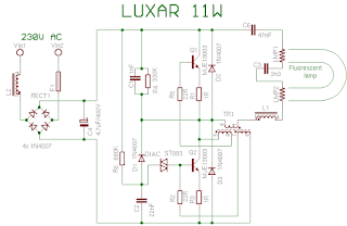
When the gas is ionisated in a pipe, C3 will be practically shorted and thanks to this frequency goes down and changer is now drived only by C6 and changer generates much lower voltage but enough to keep the light on. In a normal situation, when transistor opens, that current to TR1 increasing until his core is saturated and next his feedback to base drop away and transistor closes. Now opens second transistor which is excitated by reversly connected windind of TR1 and all process repeats.

Lamp start

Lamp start


R6, C2 and DIAC mades first pulse to base of transistor Q2 and cause his opening. After start is this section blocked by diode D1. After every opening of Q2 is discharged C2. There is not possible to collect enough energy for reopening of diac. Next are transistors excitated over very small transformer TR1. It consists of ferrite ring with three windings (5 to 10 coils). Now are filaments powered over capacitor C3 from voltage rises from resonant circuit from L1, TR1, C3 and C6. Than the tube lights up is resonation frequency specified by capacity of C3, because he has much lower capacity than C6. In this moment is voltage on a C3 over 600V in a relation to used tube. During start is peak collector current about 3 to 5 times bigger than during normal operation. When the tube is damaged, there are hazard of transistor destroying.

Electrical Contruction

Electrical construction


Princip of function we explain on a LUXAR 11W lamp. Circuit contains supply section, which includes interference suppressor L2, fuse F1, bridge rectifier from 1N4007 diodes and filtering capacitor C4. Starting section includes D1, C2, R6 and diac. D2, D3, R1, R3 have protect function. Other parts have normal operation function.

introduction

Introduction

Compact fluorescent lamps have some benefits in comparison with classic light bulbs. It is lower power consumption (to 80%) and much longer lifetime (5 to 15 times). Disadvantages are longer starts mainly at more expensive types, impossibility to use darker and price.

Fluorescent lamps are available usually in these color temperatures:

Warm white (2700K)
Cool white (4000K)
Daylight (6000K)
Most often we meet with "warm white", which is close to classic bulb and which is most pleasant to people. Compact fluorescent lamp use vacuum pipe similar to classic strip lamp and princip of energy transformation to light is same. Tube has on both ends two electrodes faced with Barium. Kathode has high temperature about 900 degree Celsius and generates many electrons which are accelerated by voltage between electrodes and hits atoms of Argon and Mercury. There arise low temperature plasm. Overflowing energy mercury radiate in a UV light form. Inner side of tube is faced with luminophore, which transform UV light in to the visible light. Tube is powered by alternating current, so that function of electrodes (cathode and anode) is still changing. Because there are used switched converter, which works on tens of kilohertz, that CFL lamp doesn't "blink" in comparison to classic strip tube lamp. Converter, which is present in a screw cap, substitute classic ballast with a starter.

CFL

Compact Fluorescent Lamp (CFL)


Menu